The usual goal of building an unobstructed reflecting telescope is to avoid a loss of contrast on planetary images. It seemed to me that allowing image aberrations to make the geometric ray trace spot as large as the diffraction spot seems to defeat the purpose. For example, in Berry's Build Your Own Telescope beginners building a small Newtonian are advised that spherical aberration causing rays to fall at the edge of the diffraction disk are about equivalent to a quarter-wave of wavefront error. This is more damaging to contrast than a small Newtonian secondary. I set a goal that all the geometrically traced rays should fall within the central quarter of the diffraction spot.
I also decided that image plane tilt is not a good thing. Most eyepieces show significantly better images at f/15 than they do at f/5. The rays from the edge of the f/5 mirror arrive at 5.7 degrees (the arctangent of 1/(5*2)) from the eyepiece optical axis. It didn't seem to me that designs with as much as nine degrees of focal plane tilt would work well. Later, I found that irt52 is capable of ray-tracing a schiefspiegler with an eyepiece, and the results are not nearly as bad as a f/3.2 Newtonian.
I looked at the designs in the instructions for Jos� Sasian's TCT program and was struck by the 20" design at the end. There are some minor challenges that I eventually eliminated. One is that the three-mirror version of the original design shows mirror-reversed images, like refractors and Schmidt-Cassegrains do when they use a diagonal mirror. I decided that adding a fourth mirror would be a good idea, to minimize confusion at the eyepiece.
Another pair of challenges was building the astigmatic ternary mirror and the flat. After a considerable amount of head scratching (and more than enough hours poking at TCT to go cross-eyed...) I tried using a pair of crossed concave mirrors, somewhat like the primary and secondary of a Yolo, to introduce astigmatism while using only spherical elements. This turned out to be surprisingly straightforward. Both mirrors have convenient radii, both are spherical, and the bother of using an auxiliary mirror to test the flat is eliminated.
The current state of the design is shown below, both in TCT and in Irt52. The original design (scaled down from 20" to 10") is shown for comparison. Both scopes have a ten inch aperture and the longest dimension (the primary to secondary spacing) is about four feet.
Light entering the scope (in the lower diagram, from the right) is reflected from a concave primary (at the left) to a convex secondary (right, just below the entering rays.) It then reflects from two concave mirrors (below left center, then near center of diagram) to the focus. The primary is partly parabolized. Its shape is 86% of the way from a sphere to a parabola. This should be fairly easy to do; the depth of the correction on the mirror is a bit less than the correction on a 6" f/8 Newtonian. The other three mirrors are spherical. The secondary and ternary have the same radius, so the ternary could be used to test the secondary by interference.
The tilts of the mirrors were (somewhat arbitrarily) constrained to total 45 degrees in the Irt52 model, so that the exiting rays are bent through 90 degrees, as in a Newtonian. If the scope is put on a Dobsonian mount with the elevation axis passing through the eyepiece, the eyepiece will remain at a constant height above the ground at all times. This would be useful if the scope were scaled up; a 20" version would have the eyepiece about four feet off the ground. For the 10" the eyepiece isn't going to be very high regardless of the mounting.
The design allows for full correction of astigmatism, coma, and line coma by adjusting the mirror tilts. The design is thus more tolerant of construction tolerances on the mirror radii than a three mirror scope can be.
There are two main concerns that I have about the design as it stands. One is that the light scattering by the four mirrors may eat into the additional contrast that was gained by making the scope unobstructed. Offhand, I don't know of any easy way of estimating this in advance, but comments in sci.astro.amateur would suggest that the mirrors will have to be unusually smooth to avoid image mushiness worse than that caused by Newtonian secondary obstruction. (There are about seven hundred total comments about schiefspieglers listed in the Deja.com search: schiefspiegler.) The other concern is that a Newtonian of around 25% larger aperture should be able to provide roughly equal contrast on details that are large enough to be visible. Of course the Newtonian, being larger, would be more sensitive to seeing. See, for example, Thierry Legault's paper on obstruction and contrast for more details on this. If anyone has any insights they would like to share, I would welcome a comment (see the link below.)
Current version of my design

DATA: fm250ki f9.2 250mm 4 mir

UNITS ARE mm, DEGREES, AND WAVES FOR COMA AND LINE COMA

Surface:  R-sag, Spacing, Tilt angle, Conic constant, R-tan, Coma, Line coma

 1    -4935.001  -1200.000    +5.37     -0.86    -4935.001     +0.00     +0.00
 2    -6350.000   +800.000   -17.36     +0.00    -6350.000     +0.00     +0.00
 3    -6350.000   -312.500   -13.00     +0.00    -6350.000     +0.00     +0.00
 4    +4424.649   +481.053   -20.01     +0.00    +4424.649     +0.00     +0.00

TRANSVERSE RAY ABERRATIONS: fm250ki f9.2 250mm 4 mir
In Airy disk diameter (AD) units: 0.013198 mm
  ON-AXIS ASTIGMATISM, COMA, AND LINE COMA:
   -0.16    +0.02    -0.02
  SPHERICAL, COMA, ASTIGMATISM, AND PETZVAL FIELD CURVATURE:
   -0.24   -1.08   +0.40   -0.35
  SAGITTAL, TANGENTIAL, DIFFERENCE, AND MEDIAL IMAGE PLANE TILTS:
  -0.59    +0.38    -0.96    -0.10   DEGREES
  ANAMORPHIC DISTORTION:
   -2.35   PERCENT

SPECIFICATIONS FOR SYSTEM fm250ki f9.2 250mm 4 mir
  F/NUMBER            9.21
  APERTURE          250.00  mm
  FOCAL LENGTH     2301.44  mm
  IMAGE DIAMETER     20.08  mm
  FIELD OF VIEW       0.50   DEGREES

DISTORTION: fm250ki f9.2 250mm 4 mir
  ANAMORPHIC           -2.35 %
  ECCENTRIC            -0.00 %
  KEYSTONE             +0.11 %
  BARREL/PINCUSHION    -0.00 %
  AT MEDIAL SURFACE TILTED   -0.10  DEGREES

CLEAR APERTURES FOR SYSTEM fm250ki f9.2 250mm 4 mir
MIRROR            CLEAR APERTURE IN mm
 1                 250.0000
 2                 145.4764
 3                 101.4940
 4                  78.5116
|
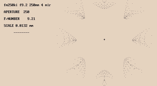
This is the spot diagram from TCT. (Click for full size.) The dashed line below "Scale 0.0132 mm" shows the Airy disk radius. The central spot is about 1/8 the Airy disk radius. A "defocus" of +.01 mm is needed to account for TCT's idea of where the focus is. |
|
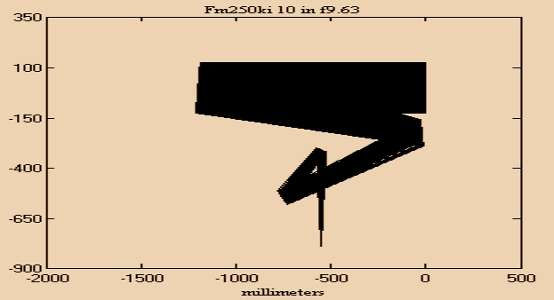
This is the ray diagram from IRT (Click for full size.) In this view, light enters the telescope from the right and the focus is at the bottom. |
And for the really stout of heart, here are the Irt52 model and the TCT file.
Jos� Sasian's Design (50% of original dimensions)

DATA: LARGE SCHIEFSPIEGLER / ATMJ # 1

UNITS ARE MM, DEGREES, AND WAVES FOR COMA AND LINE COMA

Surface:  R-sag, Spacing, Tilt angle, Conic constant, R-tan, Coma, Line coma

 1    -5176.630  -1219.429    +5.00     -1.92    -5176.630     +0.00     +0.00
 2    -5176.630   +500.000   -15.50    -17.00    -5176.630     +0.00     +0.00
 3       +0.000   -719.430   -24.00     +0.00       +0.000     +0.00     +0.00
 4    +4483.698   +944.263   -10.00     +0.00    +4119.431     +0.00     +0.00

TRANSVERSE RAY ABERRATIONS: LARGE SCHIEFSPIEGLER / ATMJ # 1
In Airy disk diameter (AD) units: 0.017916 MM
  ON-AXIS ASTIGMATISM, COMA, AND LINE COMA:
   -0.40    +0.12    -0.04
  SPHERICAL, COMA, ASTIGMATISM, AND PETZVAL FIELD CURVATURE:
   -0.20   -0.04   +0.44   -0.19
  SAGITTAL, TANGENTIAL, DIFFERENCE, AND MEDIAL IMAGE PLANE TILTS:
  +0.10    -0.16    +0.26    -0.03   DEGREES
  ANAMORPHIC DISTORTION:
   -3.07   PERCENT

SPECIFICATIONS FOR SYSTEM LARGE SCHIEFSPIEGLER / ATMJ # 1
  F/NUMBER           12.50
  APERTURE          250.00  MM
  FOCAL LENGTH     3124.15  MM
  IMAGE DIAMETER     27.26  MM
  FIELD OF VIEW       0.50   DEGREES

DISTORTION: LARGE SCHIEFSPIEGLER / ATMJ # 1
  ANAMORPHIC           -3.07 %
  ECCENTRIC            -0.02 %
  KEYSTONE             +0.04 %
  BARREL/PINCUSHION    -0.00 %
  AT MEDIAL SURFACE TILTED   -0.03  DEGREES
The instructions for this program (in Windows Write format; it can be opened with Wordpad) include the optical design for his 20" large three-mirror TCT (Tilted Component Telescope, the English equivalent of schiefspiegler.)
This program is probably essential to any attempt to build one of these telescopes, since there will inevitably be minor differences between the original design for the mirrors and what is actually fabricated. Without ray-tracing software it is not easy to determine which errors can be accepted as trivial and which will undermine the performance of the finished scope. The program can be downloaded here from David Stevick's Weird Telescopes page, along with several other ray-tracing programs.
IRT can drive you totally mad (hint: if you're running Windows 95 plan on rebooting really really often; it works much better under NT 4.0!) However, it can optimize a design better than TCT's can, and it can raytrace eyepieces. A evaluation copy of the program is available here from David Stevick's alma mater.
You can comment, leave messages, or start a discussion here.
You can email me at or visit my homepage at http://www.fortunecity.com/tatooine/yoda/194/ .
This page was last modified .